


| Quantity: | |
|---|---|
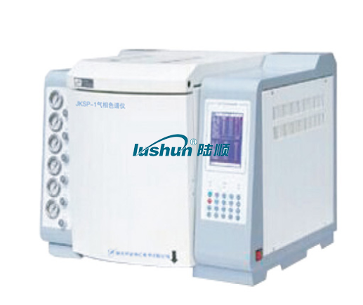
LSSP-1
Lshun
1.Product Introduction
TheLSSP-1 gas chromatograph is a special-purpose gas chromatographic analyzer designed and manufactured for the power system in accordance with the recommended gas chromatographic analysis procedures specified in the following national standards: GB/T 30431-2020 Laboratory Gas Chromatographs, GB/T 17623-2017 Determination of Dissolved Gas Components in Insulating Oil by Gas Chromatography, and GB/T 7252-2001 Guidelines for Analysis and Judgment of Dissolved Gases in Transformer Oil.
It adopts a three-detector flow path design, featuring one-time sample injection, dual-column parallel configuration, and secondary split flow control. The TCD (Thermal Conductivity Detector) is used for detecting H₂ and O₂ (N₂), while the FID (Flame Ionization Detector) is employed to detect CO, CO₂, and hydrocarbon gases. It can fully meet customers' requirements in terms of detection sensitivity, chromatographic peak resolution, and quantitative accuracy.
2.Product Features
(1)It adopts a 7.0-inch 1024×600 color touch screen with a Chinese character display interface and full-screen touch keys. Temperature control and flow adjustment are displayed synchronously, making parameter setting and operation intuitive and convenient.
(2) It adopts an adaptive PID temperature control circuit and high-performance temperature sensors. The stability of the set temperature is not more than 0.5%, which ensures the repeatability of the analysis results.
(3) It adopts computerized operation, equipped with an Ethernet communication interface and a built-in IP protocol stack to realize PC data transmission, facilitating the management of analytical data.
(4)It adopts high-voltage electronic ignition technology to realize programmable automatic timed ignition for dual-channel FID. A current detection circuit is integrated to monitor ignition stability in real time.
(5) It adopts a configuration with one thermal conductivity detector and two flame ionization detectors, enabling synchronous output of three-channel signals.
(6)It adopts a TCD automatic analysis system, which intelligently monitors the carrier gas pressure and flow in real time. When an abnormal condition occurs, it will automatically cut off the bridge current circuit, thereby protecting the instrument and detection equipment.
3. Technical Specifications
Column Oven Temperature Control
(1) Temperature Control Range: 10℃ above room temperature to 350℃
(2) Temperature Stability: Not more than 0.5%
(3) Temperature Deviation: Not exceeding ±3%
(4) Programmed Temperature Repeatability: Not more than 1%
Flame Ionization Detector (FID)
(1) Temperature control range: 10℃ above room temperature to 200℃
(2) Detection Limit: ≤1×10-11 g/s
(3) Baseline Drift: ≤1×10-11 A
(4) Baseline Noise: ≤1×10-12 A
Thermal Conductivity Detector (TCD)
(1) Temperature Control Range: 10℃ above room temperature to 200℃
(2) Detection Limit: ≤ 1×10-11 g/s
(3) Sensitivity: ≥ 2000 mV·mL/mg
(4) Baseline Drift: ≤ 0.2 mV
(5) Baseline Noise: ≤ 0.1 mV
Startup Time: ≤ 2 h
Qualitative Repeatability: ≤ 1%
Quantitative Repeatability: ≤ 3%
Environmental Temperature: 5 °C ~ +35 °C
Relative Humidity: 20% ~ 80%
Power Supply Voltage: AC 220V±22V
Power Supply Frequency: 50Hz±2.5Hz
Maximum Power Consumption: 2 kW
Overall Dimensions and Weight
· Overall Dimensions: 570×550×470(mm)
· Weight: 48kg
VRP Series Varnish Removal Oil Purifier
Application
Used in gas and steam turbine, compressor, to remove dissolved and suspended soft pollutants in oil products, sludge and other harmful substances. Avoid turbine failures and expensive oil changes due to paint film problems. When the film is formed, the loss of production is very high. The initial formation of the film is known as a soft pollutant, caused by hot spots in the system, such as bearings, pumps, and high flow on-line filtration. Recent studies have found that the existence of soft pollutants can be divided into dissolved state and suspended state, by removing these soft oxides can avoid the production of paint film. Once the film forms, it will clog valves, filters and other small links, and the life of the oil will be significantly reduced.
The formation of cleaning film will cause the following adverse consequences: valve adhesion, loss of control, resulting in unit failure or startup failure; Filter plugging, limiting oil flow, resulting in oil temperature rise and wear increase; Heat exchange failure, oil temperature rise; Sandpaper surface, increase component wear; Forming paint on the bearing, limiting flow, increasing wear and temperature; Frequent oil changes and system flushes. When the soft pollutants are dissolved in the oil, typically when the oil temperature is above 40℃, they cannot be removed by ordinary mechanical filtration or electrostatic filtration, and these soft pollutants show natural magnetism. For polar absorption, the cooler metal surface "cold spot", i.e. the valve and cooler. When the temperature of the oil is lowered, the thermal stability of the soft pollutants is less than that of the oil, so they are more likely to bake hard on hot surfaces, such as axial shafts.
VRP paint film cleaner. It achieves revolutionary and efficient removal of soft pollutants (dissolved and suspended) from oil products, including gas and steam turbines and compressors under high temperature operation. The warm oil is pumped from the lowest point at the bottom of the tank to the VRP paint film purifier by the equipment's own transfer pump. After cooling treatment (using the thermal stability of the paint film is worse than that of oil), the paint film, particulate matter and moisture are removed by the filter element with wood fiber as the raw material (no need to use ion-exchange resin filter material, greatly saving the cost of use).
Features:
● Increase system reliability and stability. ● No more shutdowns and startup failures caused by paint film.
● No longer need to clean the tank and system flushing. ● Increase jacking oil pressure, more stable bearing temperature.
● Improve the life of oil products, blood additives and system components, such as bearings, valves, seals, etc.
● Great savings can be achieved by avoiding turbine failure and extending the life of oil products. Features:
● Increase system reliability and stability. ● No more shutdowns and startup failures caused by paint film.
● No longer need to clean the tank and system flushing. ● Increase jacking oil pressure, more stable bearing temperature.
● Improve the life of oil products, blood additives and system components, such as bearings, valves, seals, etc.
● Great savings can be achieved by avoiding turbine failure and extending the life of oil products.
Technical Specification
|
Model |
VRP-10 |
|
Flow |
10L/min |
|
Working Pressure |
≤0.5Mpa |
|
Total Power |
5.55KW |
|
Power Supply |
AC380V/50Hz |
|
Overall Dimension |
1466mm×1126mm×1750mm |
|
Net Weight |
500kg |
|
Particle contamination degree(NAS1638)
|
≤6grade |
|
MPC data |
<15 |
■Above size and weight of this equipment are for reference only, the specific data shall be subject to its physical object.


 渝公网安备 50010702502819号