


| Quantity: | |
|---|---|
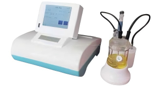
LSWT-3200
1. GB/T 26793-2011 Coulometric Karl Fischer Moisture Analyzer
2. GB/T 606-2003 Chemical Reagents — General Method for the Determination of Water — Karl Fischer Method
3. GB/T 7600-2014 Determination of Water Content in Transformer Oil in Service (Coulometric Method)
4. GB/T 3727-2003 Determination of Trace Water in Ethylene and Propylene for Industrial Use
5. GB/T 6023-2008 Industrial Use Butadiene — Determination of Trace Water — Coulometric Karl Fischer Method
6. GB/T 6283-2008 Determination of Water Content in Chemical Products — Karl Fischer Method (General Method)
7. GB/T 11146-2009 Determination of Water Content in Crude Oil (Coulometric Karl Fischer Method)
8. GB/T 7376-2008 Determination of Trace Water in Industrial Chlorinated Alkanes
9. GB/T 18619.1-2002 Determination of Water Content in Natural Gas — Coulometric Karl Fischer Method
10. SH/T 0246-1992 Determination of Water Content in Light Petroleum Products (Electricity Method)
11. SH/T 0255-1992 Determination of Water Content in Additives and Additized Lubricating Oils (Electricity Method)
Main technical specifications:
1. Resolution: 0.1 μg
2. Electrolysis Current: Max. 360 mA
3. Control System: Microcontroller (MCU)
4. Measurement Range: 2.5 μg ~ 100 mg (Water)
5. Display Interface: Color LCD touch screen displaying water content (μg), measurement potential, electrolysis current, concentration, clock, stirring status, speed level, etc.
6. Communication Function: Capable of connecting to an external electronic balance or computer.
7. Output Method: Embedded miniature thermal printer printing analysis time, trace water value, sample concentration, and sample quantity parameters.
8. Zero Calibration: Powerful software blank subtraction function ensures the instrument status value drops within the equilibrium range, allowing sample analysis after 2 minutes.
9. Fault Diagnosis: Automatically displays the fault location when an error occurs in the electrolysis or measurement section.
10. Stirring Method: Magnetic stirring with speed digitally adjustable.
11. Optimized equilibrium point can be manually or automatically adjusted according to reagents of different sensitivities to optimize the analysis process.
12. Accuracy:
1. 2.5 μg water: ±20%
2. 10 μg water: ±10%
3. 100 μg water: ±1%
4. Above 100 μg water: ±0.5% (excluding injection error)
VRP Series Varnish Removal Oil Purifier
Application
Used in gas and steam turbine, compressor, to remove dissolved and suspended soft pollutants in oil products, sludge and other harmful substances. Avoid turbine failures and expensive oil changes due to paint film problems. When the film is formed, the loss of production is very high. The initial formation of the film is known as a soft pollutant, caused by hot spots in the system, such as bearings, pumps, and high flow on-line filtration. Recent studies have found that the existence of soft pollutants can be divided into dissolved state and suspended state, by removing these soft oxides can avoid the production of paint film. Once the film forms, it will clog valves, filters and other small links, and the life of the oil will be significantly reduced.
The formation of cleaning film will cause the following adverse consequences: valve adhesion, loss of control, resulting in unit failure or startup failure; Filter plugging, limiting oil flow, resulting in oil temperature rise and wear increase; Heat exchange failure, oil temperature rise; Sandpaper surface, increase component wear; Forming paint on the bearing, limiting flow, increasing wear and temperature; Frequent oil changes and system flushes. When the soft pollutants are dissolved in the oil, typically when the oil temperature is above 40℃, they cannot be removed by ordinary mechanical filtration or electrostatic filtration, and these soft pollutants show natural magnetism. For polar absorption, the cooler metal surface "cold spot", i.e. the valve and cooler. When the temperature of the oil is lowered, the thermal stability of the soft pollutants is less than that of the oil, so they are more likely to bake hard on hot surfaces, such as axial shafts.
VRP paint film cleaner. It achieves revolutionary and efficient removal of soft pollutants (dissolved and suspended) from oil products, including gas and steam turbines and compressors under high temperature operation. The warm oil is pumped from the lowest point at the bottom of the tank to the VRP paint film purifier by the equipment's own transfer pump. After cooling treatment (using the thermal stability of the paint film is worse than that of oil), the paint film, particulate matter and moisture are removed by the filter element with wood fiber as the raw material (no need to use ion-exchange resin filter material, greatly saving the cost of use).
Features:
● Increase system reliability and stability. ● No more shutdowns and startup failures caused by paint film.
● No longer need to clean the tank and system flushing. ● Increase jacking oil pressure, more stable bearing temperature.
● Improve the life of oil products, blood additives and system components, such as bearings, valves, seals, etc.
● Great savings can be achieved by avoiding turbine failure and extending the life of oil products. Features:
● Increase system reliability and stability. ● No more shutdowns and startup failures caused by paint film.
● No longer need to clean the tank and system flushing. ● Increase jacking oil pressure, more stable bearing temperature.
● Improve the life of oil products, blood additives and system components, such as bearings, valves, seals, etc.
● Great savings can be achieved by avoiding turbine failure and extending the life of oil products.
Technical Specification
|
Model |
VRP-10 |
|
Flow |
10L/min |
|
Working Pressure |
≤0.5Mpa |
|
Total Power |
5.55KW |
|
Power Supply |
AC380V/50Hz |
|
Overall Dimension |
1466mm×1126mm×1750mm |
|
Net Weight |
500kg |
|
Particle contamination degree(NAS1638)
|
≤6grade |
|
MPC data |
<15 |
■Above size and weight of this equipment are for reference only, the specific data shall be subject to its physical object.


 渝公网安备 50010702502819号