

空气中的主要组份是氮和氧,因此可选择对氮和氧具有不同吸附选择性的吸附剂,设计适当的工艺过程,使氮和氧分离制得氮气。
氮和氧都具有四极矩,但氮的四极矩(0.31Å)比氧的(0.10 Å)大得多,而在一定压力下,氧气在碳分子筛中被吸附的能力比氮气强得多(氧与分子筛表面离子的作用力强,如图1所示)。因此,当空气在加压状态下通过装有碳分子筛吸附剂的吸附床时,氧气被分子筛吸附,氮气因吸附较少,在气相中得到富集并流出吸附床,使氧气和氮气分离获得氧气。当分子筛吸附氧气至接近饱和时,停止通空气并降低吸附床的压力,分子筛吸附的氧气可以解吸出来,分子筛得到再生并重复利用。两个以上的吸附床轮流切换工作,便可连续生产出氮气。如下图所示,A为氧气,B为氮气。
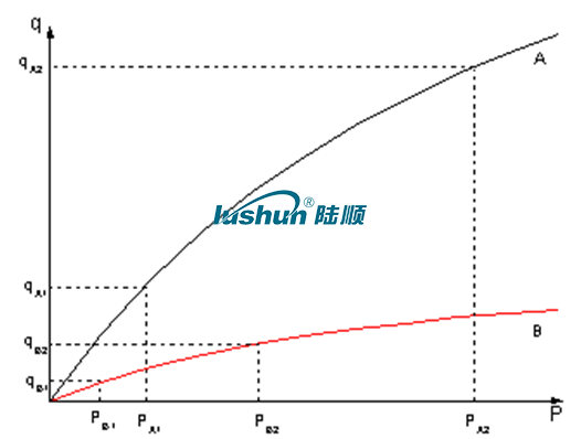
原理示意图
空压机系统:首先第一步原料空气经压缩机压缩至≥0.8-1.0Mpa(表压,稳定值),
排气温度≤45℃,排气含油量≤3PPm,排气含尘量≤3μm。
空气缓冲系统:压缩空气首先进入空气缓冲罐,初次降温排水,稳定输出压力。
压缩空气净化系统:压缩空气从空气缓冲罐出来后,先经过高效除油器、冷冻
式干燥机、吸附式干燥机,主管路过滤器、微油雾过滤器、粉尘过滤器、超
高效微油雾过滤器等空气净化设备除去压缩空气中的油、水、尘,使压缩空
气压力露点达到2-10℃,油含量≤0.003PPm、温度≤38℃、含尘滤径≤0.01um。经净化的压缩空气进入空气工艺罐。
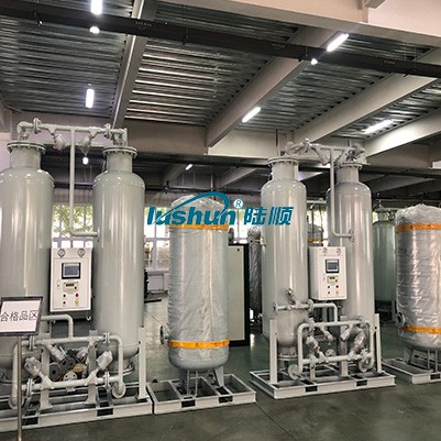
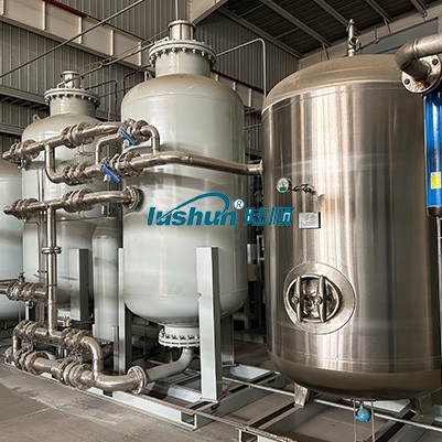
PSA制氮及过滤系统:从空气工艺罐出来的洁净压缩空气,进入二个填装吸附
剂(复合床结构)的变压吸附分离系统,洁净的压缩空气由吸附塔底端进入,气
流经特殊的空气扩散器扩散以后,均匀进入吸附塔,进行氧氮吸附分离,然后从
出口端流出氮气,进入氮气缓冲罐,经氮气过滤器的再次过滤后,产氮过程结束
后,再经均压和减压(至常压),吸附剂脱附所吸附的杂质组分(主要为O2及
少量CO2、H2O),完成吸附剂的再生。二个吸附塔交替循环操作,连续送入原
料空气,连续生产指标满足生产需要的氮气。
制氮设备标配功能:
1. 氮气纯度、流量、压力在线监测
2. 程控阀门切换由可编程序控制器自动控制
3. 不合格氮气长时报警自动停机功能
4. 分子筛自动压紧、下沉报警及极限关机保护
5. 过滤器自动排污
6. 不合格氮气声光报警并自动放空
7. 触摸屏人机界面
8. 预留支持RS485通讯接口
设备技术特点:
经过20多年的技术积累与市场应用,坚持研发与创新,始终保持核心技术领先,致力为用户提供最优的气体解决方案。
Ø 系统运行环境为低压或常压,安全、便捷;
Ø 设备结构简单,维护简便,运行成本低。
Ø PLC控制,全自动无人操作。
Ø 设备一次性可产出氮气纯度99.999%,氮气纯度可以随流量的变化进行调节。
Ø 研发团队对吸附剂均进行了严格测试,最大可能提高吸附剂的利用效率,极致节能,设备耗气量仅为行业平均水平的70%。
Ø 最全面、最严格的吸附剂保护技术,不断优化系统流程,最大限度保证设备稳定性。
Ø 最先进的控制系统,PC级操作,实现系统设备全自动化、流程监控、远程就地切换、压力启停控制、仪表与传感器校准、节能负荷适应等多项实用功能。
Ø 系统设计合理,结构紧凑,占地面积最小。
Ø 设备启动快,在开机30分钟后即可供气。
并可根据项目情况提供个性化,定制化设计方案,满足客户的实际需求。
VRP Series Varnish Removal Oil Purifier
Application
Used in gas and steam turbine, compressor, to remove dissolved and suspended soft pollutants in oil products, sludge and other harmful substances. Avoid turbine failures and expensive oil changes due to paint film problems. When the film is formed, the loss of production is very high. The initial formation of the film is known as a soft pollutant, caused by hot spots in the system, such as bearings, pumps, and high flow on-line filtration. Recent studies have found that the existence of soft pollutants can be divided into dissolved state and suspended state, by removing these soft oxides can avoid the production of paint film. Once the film forms, it will clog valves, filters and other small links, and the life of the oil will be significantly reduced.
The formation of cleaning film will cause the following adverse consequences: valve adhesion, loss of control, resulting in unit failure or startup failure; Filter plugging, limiting oil flow, resulting in oil temperature rise and wear increase; Heat exchange failure, oil temperature rise; Sandpaper surface, increase component wear; Forming paint on the bearing, limiting flow, increasing wear and temperature; Frequent oil changes and system flushes. When the soft pollutants are dissolved in the oil, typically when the oil temperature is above 40℃, they cannot be removed by ordinary mechanical filtration or electrostatic filtration, and these soft pollutants show natural magnetism. For polar absorption, the cooler metal surface "cold spot", i.e. the valve and cooler. When the temperature of the oil is lowered, the thermal stability of the soft pollutants is less than that of the oil, so they are more likely to bake hard on hot surfaces, such as axial shafts.
VRP paint film cleaner. It achieves revolutionary and efficient removal of soft pollutants (dissolved and suspended) from oil products, including gas and steam turbines and compressors under high temperature operation. The warm oil is pumped from the lowest point at the bottom of the tank to the VRP paint film purifier by the equipment's own transfer pump. After cooling treatment (using the thermal stability of the paint film is worse than that of oil), the paint film, particulate matter and moisture are removed by the filter element with wood fiber as the raw material (no need to use ion-exchange resin filter material, greatly saving the cost of use).
Features:
● Increase system reliability and stability. ● No more shutdowns and startup failures caused by paint film.
● No longer need to clean the tank and system flushing. ● Increase jacking oil pressure, more stable bearing temperature.
● Improve the life of oil products, blood additives and system components, such as bearings, valves, seals, etc.
● Great savings can be achieved by avoiding turbine failure and extending the life of oil products. Features:
● Increase system reliability and stability. ● No more shutdowns and startup failures caused by paint film.
● No longer need to clean the tank and system flushing. ● Increase jacking oil pressure, more stable bearing temperature.
● Improve the life of oil products, blood additives and system components, such as bearings, valves, seals, etc.
● Great savings can be achieved by avoiding turbine failure and extending the life of oil products.
Technical Specification
|
Model |
VRP-10 |
|
Flow |
10L/min |
|
Working Pressure |
≤0.5Mpa |
|
Total Power |
5.55KW |
|
Power Supply |
AC380V/50Hz |
|
Overall Dimension |
1466mm×1126mm×1750mm |
|
Net Weight |
500kg |
|
Particle contamination degree(NAS1638)
|
≤6grade |
|
MPC data |
<15 |
■Above size and weight of this equipment are for reference only, the specific data shall be subject to its physical object.


 渝公网安备 50010702502819号